X
A portable power supply has become the lifeline of the modern technological world, especially the lithium-ion battery. In this article we’ll give a conceptual introduction of Lithium-ion battery and its working.
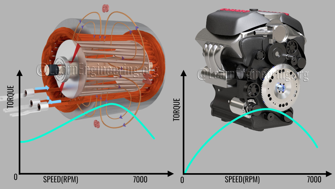
Imagine a world where all cars are driven by induction motors and not internal combustion engines. Induction motors are far superior to IC engines in almost all engineering aspects, as well as being more robust and cheaper. Another huge disadvantage of IC engines is that they only produce usable torque in a narrow band of engine RPM. Considering all of these factors, induction motors are definitely the perfect choice for an automobile.(Fig:1)
Very few moving parts
No balancing issues
Good speed control
High Acceleration
Self started
High starting torque
Thousands of moving parts
Mechanical balancing issue
Poor speed control
Low acceleration
Not self started
Low starting torque
However, the power supply for an induction motor is the real bottleneck in achieving a major induction motor revolution in the automobile industry. Let’s explore how Tesla, with the help of lithium-ion cells, solved this issue and why lithium-ion cells are going to become even better in the future (Fig:2).
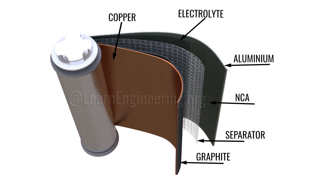
Let’s take a Tesla cell out from the battery pack and break it down. You can see different layers of chemical compounds inside it (Fig:3). Tesla’s lithium-ion battery works on an interesting concept associated with metals, called the electrochemical potential. Electrochemical potential is the tendency of a metal to lose electrons.
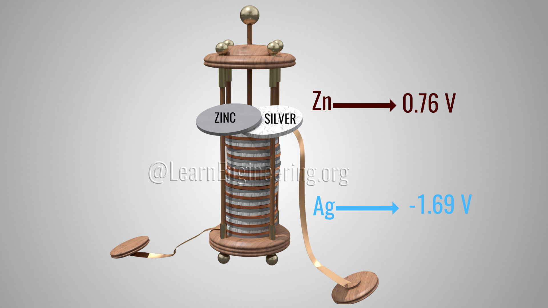
In fact, the very first cell(Fig:4), developed by Alessandro Volta, more than 200 years ago was based on the concept of electrochemical potential. A general electrochemical series is shown here. According to these values, lithium has the highest tendency to lose electrons, and fluorine has the least tendency to lose electrons. Volta took two metals with different electrochemical potentials, in this case, zinc and silver and created an external flow of electricity.
Sony made the first commercial model of a lithium-ion battery in 1991. It was again based on the same concept of electrochemical potential. Lithium, which has the highest tendency to lose electrons, was used in lithium-ion cells. Lithium has only one electron in its outer shell and always wants to lose this electron. Due to this reason pure lithium is a highly reactive metal (Fig:5). It even reacts with water and air.
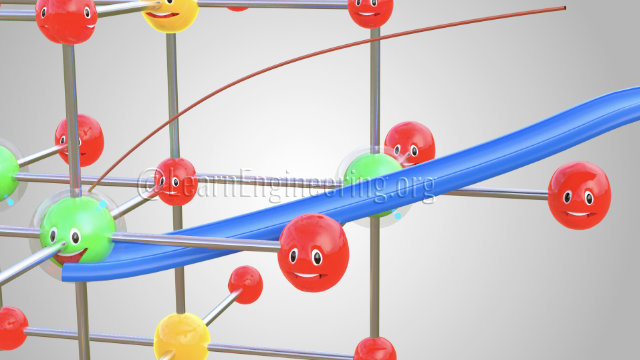
The trick of a lithium-ion battery operation is the fact that lithium, in its pure form, is a reactive metal, but when lithium is part of a metal oxide it is quite stable. Assume that somehow, we have separated a lithium atom from this metal oxide. This lithium atom is highly unstable and will instantly form a lithium ion and an electron. However, lithium as a part of metal oxide is much more stable than this state (Fig:6A). If you can provide two different paths for the electron and lithium-ion flow between the lithium and the metal oxide, the lithium atom will automatically reach the metal oxide part. During this process we have produced electricity from the electron flow through the one path (Fig:6B). From these discussions it is clear that we can produce electricity from this lithium metal oxide, if we firstly separate out lithium atoms from the lithium metal oxide, and secondly guide the electrons lost from such lithium atoms, through an external circuit. Let’s see how lithium-ion cells achieve these two objectives
A practical lithium-ion cell also uses an electrolyte and graphite. Graphite has a layered structure. These layers are loosely bonded so that the separated lithium ions can be stored very easily there. The electrolyte, between the graphite and the metal oxide, acts as a guard which allows only lithium ions through (Fig:7).
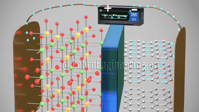
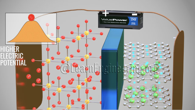
Now let’s see what happens when you connect a power source across this arrangement. The positive side of the power source will obviously attract and remove electrons from the lithium atoms of the metal oxide. These electrons flow through the external circuit as they cannot flow through the electrolyte and reach the graphite layer (Fig:8A). In the meantime, the positively charged lithium-ions will be attracted towards the negative terminal and will flow through the electrolyte. Lithium-ions also reach the graphite layer space and get trapped there. Once all the lithium atoms reach the graphite sheet, the cell is fully charged. Thus, we have achieved the first objective, which is the lithium ions and electrons detached from the metal oxide. As we discussed, this is an unstable state, as if being perched on top of a hill (Fig:8B).
As soon as the power source is removed, and a load is connected, the lithium ions want to go back to their stable state as a part of the metal oxide. Due to this tendency, the lithium ions move through the electrolyte and electrons via the load, just like sliding down a hill. Thus, we get an electrical current through the load (Fig:9).
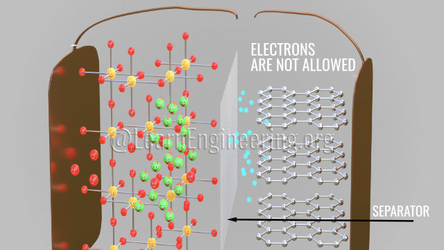
Please note that the graphite does not have a role in the chemical reaction of the lithium-ion cells. Graphite is just a storage medium for lithium ions. If the internal temperature of the cell rises due to some abnormal condition, the liquid electrolyte will dry up and there will be a short circuit between the anode and cathode, and this can lead to a fire or an explosion (Fig:10A). To avoid such a situation, an insulating layer, called a separator, is placed between the electrodes. The separator is permeable for the tiny lithium-ions because of its micro-porosity (Fig:10B).
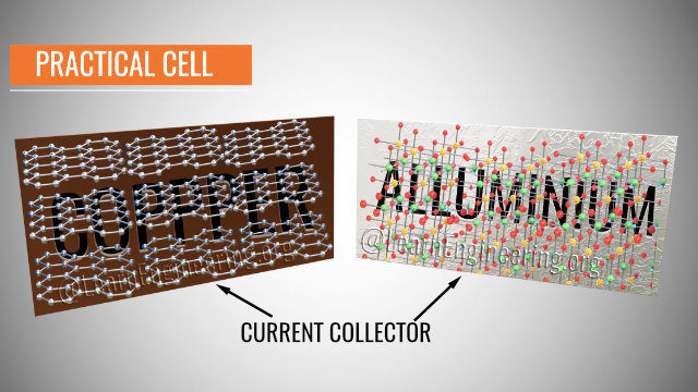
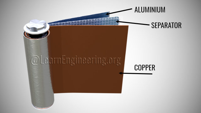
In a practical cell, the graphite and metal oxide are coated onto copper and aluminum foils (Fig:11A). The foils act as current collectors here, and the positive and negative tabs can be easily taken out from the current collectors. An organic salt of lithium acts as the electrolyte, and it is coated onto the separator sheet. All these three sheets are wound onto the cylinder, around a central steel core, thus making the cell more compact (Fig:11B).
A standard Tesla cell has a voltage of between 3 and 4.2 Volts. Many such Tesla cells are connected in series and in a parallel fashion to form a module. 16 such modules are connected in series to form a battery pack in the Tesla car. Lithium-ion cells produce a lot of heat during the operation and a high temperature will decay the cell’s performance.
A Battery Management System is used to manage the temperature, state of charge, voltage protection, and cell health monitoring of such a huge number of cells. Glycol based cooling technology is used in a Tesla battery pack (Fig:12A). The BMS adjusts the glycol flow rate to maintain the optimum battery temperature. Voltage protection is another crucial job of the BMS. For example, in these three cells, during charging, the higher capacity cell will be charged more than the rest. To solve this problem, the BMS uses something called “cell balancing”. In cell balancing, all the cells are allowed to charge and discharge equally, thus protecting them from over and under voltage (Fig:12B).
This is where Tesla scores over Nissan battery technology (Fig:13). The Nissan Leaf has a huge battery cooling issue due to the big size of its cells and the absence of an active cooling method. The small, multiple, cell design has one more advantage. During high power demand situations, the discharge strain will be divided equally among each of the cells. Instead of many small cells, if we had used a single giant cell, it would have been put under a lot of strain, and eventually it would suffer a premature death. By using many small cylindrical cells, the manufacturing technology of which is already well established, Tesla clearly made a winning decision.
There is a magical phenomenon, which happens within lithium-ion cells during their very first charge, that saves the lithium-ion cells from sudden death. Let’s see what it is. The electrons in the graphite layer are a major problem. The electrolyte will be degraded if the electrons come into contact with it (Fig:14A). However, the electrons never come into contact with the electrolyte due to an accidental discovery, the Solid Electrolyte Interface. When you charge the cell for the first time, as explained above, the lithium-ions move through the electrolyte. Here, in this journey, solvent molecules, in the electrolyte, cover the lithium-ions. When they reach the graphite, the lithium-ions, along with the solvent molecules, react with the graphite and form a layer there called the “SEI layer”. The formation of this SEI layer is a blessing in disguise (Fig:14B); it prevents any direct contact between the electrons and the electrolyte, thus saving the electrolyte from degradation. In this overall process of the formation of the SEI layer, it will consume 5% of the lithium. The remaining 95% of the lithium contributes to the main working of the battery. Even though the SEI layer was an accidental discovery, with over two decades of research and development, scientists have optimized the thickness and chemistry of the SEI layer for maximum cell performance.
It is amazing to find out that those electronic gadgets we used around two decades back did not use lithium-ion batteries. With its amazing speed of growth, the lithium-ion battery market is expected to become a 90-billion-dollar annual industry within a few years.
The currently achieved number of charge-discharge cycles of a lithium-ion battery is around 3,000. Great minds across the globe are putting their best efforts into increasing this to 10,000 cycles. That means you would not have to worry about replacing the battery in your car for 25 years. Millions of dollars have already been invested in research into replacing the storage medium graphite with silicon (Fig:15A ). If this is successful, the energy density of the lithium-ion cell will increase by more than 5 times.
This article is written by Ravindra Kempaiah,
Researcher PHD Student, University of Illinois, Chicago.
He is an Energy storage materials (batteries, electrodes) and EV enthusiast. To know more about the author
check this link
Copyright ©2021 Lesics Engineers Pvt.Ltd All Rights Reserved